Tier-1 Service Provider Architecture and L3VPN
A Tier-1 service provider backbone separates customer complexity from core transport through a layered architecture: IS-IS provides reachability between loopbacks [5, 6], MPLS LDP builds label-switched paths over that underlay [8, 10], and MP-BGP with VRFs delivers per-customer L3VPN services at the edge [2]. This design allows P routers in the core to forward millions of customer packets using only a handful of transport labels, while all routing intelligence lives on PE routers at the network perimeter [13, 14].
Content
Network Topology and Router Roles
A reference Tier-1 SP backbone operating in AS 65000 consists of three device classes:
- Provider Edge (PE) routers — the customer-facing boundary. Each PE runs BGP sessions toward customer equipment (CE routers) [1] and iBGP sessions toward route reflectors [4]. PEs host VRF instances that isolate each customer’s routing table [2]. In this reference design there are four: PE1 (10.0.0.11), PE2 (10.0.0.12), PE3 (10.0.0.13), and PE4 (10.0.0.14).
- Provider (P) routers — pure transit nodes. P routers run only the IGP (IS-IS) and MPLS; they never see a customer prefix. They label-switch packets based solely on LDP-assigned transport labels [8, 10]. The reference topology uses two: P1 (10.0.0.1) and P2 (10.0.0.2).
- Route Reflector (RR) — eliminates the iBGP full-mesh requirement among PEs [4]. RR1 (10.0.0.100) peers with every PE and reflects VPNv4 routes between them [2, 4]. Production networks deploy at least two RRs for redundancy.
Every router carries a /32 loopback address — the most operationally significant address on the device, used as the BGP router-id, MPLS LDP router-id, and tunnel endpoint. All inter-router links use /31 point-to-point subnets to conserve address space.
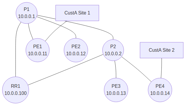
graph TD
    P1(("P1<br/>10.0.0.1"))
    P2(("P2<br/>10.0.0.2"))
    PE1(("PE1<br/>10.0.0.11"))
    PE2(("PE2<br/>10.0.0.12"))
    PE3(("PE3<br/>10.0.0.13"))
    PE4(("PE4<br/>10.0.0.14"))
    RR1(("RR1<br/>10.0.0.100"))
    CA1["CustA Site 1"]
    CA2["CustA Site 2"]

    CA1 --- PE1
    CA1 --- PE2
    PE1 --- P1
    PE2 --- P1
    PE2 --- P2
    P1 --- P2
    P2 --- PE3
    P2 --- PE4
    CA2 --- PE4
    RR1 --- PE1
    RR1 --- PE2
    RR1 --- PE3
    RR1 --- PE4
    RR1 --- P1
IS-IS as the Underlay IGP
Tier-1 providers overwhelmingly choose IS-IS over OSPF for the backbone underlay [13, 14]. Three properties drive this preference: IS-IS runs directly over Layer 2 (reducing the IP-level attack surface) [7], it scales more gracefully under large route counts, and a single IS-IS instance handles both IPv4 and IPv6 natively [6].
The backbone operates as a flat Level-2-only domain — there is no Level-1/Level-2 hierarchy within the core.
Reference PE configuration (PE1):
router isis CORE
 net 49.0001.0100.0000.0011.00
 is-type level-2-only
 metric-style wide
 log-adjacency-changes
 passive-interface Loopback0
!
interface Loopback0
 ip address 10.0.0.11 255.255.255.255
 ip router isis CORE
!
interface GigabitEthernet0/0
 ip address 10.1.1.0 255.255.255.254
 ip router isis CORE
 isis network point-to-point
 isis metric 10
Key configuration elements:
- NET (Network Entity Title) follows the format
49.area.system-id.00. The AFI49denotes a private address space,0001is the area identifier,0100.0000.0011encodes the loopback IP, and00is the NSEL (always zero on a router) [6, 7]. metric-style wideenables 24-bit metrics [5]. The legacy 6-bit default is insufficient for modern traffic-engineering calculations [5].passive-interface Loopback0injects the loopback prefix into the IS-IS link-state database without attempting to form an adjacency on the loopback interface.isis network point-to-pointon physical links bypasses Designated Intermediate System (DIS) election, which is unnecessary overhead on point-to-point connections.
Verification:
PE1# show isis neighbors
PE1# show ip route 10.0.0.14
i L2  10.0.0.14/32 [115/30] via 10.1.1.1, GigabitEthernet0/0
The [115/30] output confirms IS-IS Level-2 with administrative distance 115 and a composite metric of 30.
MPLS LDP in the Core
Label Distribution Protocol (LDP) assigns a local label to every IGP-learned prefix and advertises these bindings to its neighbors [10]. The result is a set of label-switched paths (LSPs) connecting every pair of loopback addresses across the backbone [8, 10]. Once an LSP exists, any packet entering the core with a label header is forwarded purely by label lookup — no IP header inspection occurs at transit hops [8, 9].
Enabling MPLS on a PE:
mpls label protocol ldp
mpls ldp router-id Loopback0 force
!
interface GigabitEthernet0/0
 mpls ip
The router-id Loopback0 force directive anchors LDP sessions to the loopback, ensuring they survive individual link failures. The mpls ip command on each core-facing interface activates label imposition and disposition on that link.
Verification:
PE1# show mpls forwarding-table 10.0.0.14
Local  Outgoing  Prefix        Outgoing  Next Hop
16     20        10.0.0.14/32  Gi0/0     10.1.1.1
This output shows that packets destined for PE4’s loopback (10.0.0.14/32) arrive with local label 16, are swapped to outgoing label 20, and forwarded out GigabitEthernet0/0. MPLS label switching is the foundation for all overlay services: L3VPN, L2VPN, traffic engineering, and fast reroute [8, 9].
iBGP and the VPNv4 Route Reflector
PEs establish iBGP sessions to RR1 using loopback addresses (ensuring session stability independent of any single physical path) [1]. RR1 operates as a VPNv4 route reflector — it receives VPNv4 updates from each PE and reflects them to all other PEs, eliminating the O(n^2) full-mesh requirement [4].
RR1 configuration:
router bgp 65000
 bgp router-id 10.0.0.100
 neighbor SP-PES peer-group
 neighbor SP-PES remote-as 65000
 neighbor SP-PES update-source Loopback0
 neighbor 10.0.0.11 peer-group SP-PES
 neighbor 10.0.0.12 peer-group SP-PES
 neighbor 10.0.0.13 peer-group SP-PES
 neighbor 10.0.0.14 peer-group SP-PES
 !
 address-family vpnv4
  neighbor SP-PES activate
  neighbor SP-PES route-reflector-client
  neighbor SP-PES send-community extended
 exit-address-family
The route-reflector-client directive under address-family vpnv4 tells RR1 to reflect VPNv4 routes learned from one PE client to every other PE client [4]. Extended communities must be forwarded (send-community extended) because Route Targets — the mechanism that controls VPN route import/export — are carried as extended BGP communities [2]. Only the VPNv4 address family is activated here; this is a dedicated MPLS VPN deployment [2].
Building an L3VPN Service
An L3VPN connects multiple customer sites through the SP backbone as if they shared a private routed network. The following walkthrough provisions service for Customer A, which has sites attached to PE1 and PE4.
Step 1: Define the VRF
A Virtual Routing and Forwarding (VRF) instance on each PE creates an isolated routing table for the customer [2].
vrf definition CUST-A
 rd 65000:100
 address-family ipv4
  route-target export 65000:100
  route-target import 65000:100
 exit-address-family
Three identifiers govern VRF behavior:
- Route Distinguisher (RD)
65000:100— prepended to every IPv4 prefix learned in this VRF, producing a globally unique VPNv4 prefix [2]. This allows multiple customers to use identical private address space (e.g., both using 192.168.1.0/24) without collision in the provider’s BGP table [2]. - Route Target export
65000:100— an extended community attached to every route advertised from this VRF [2]. It declares “this route belongs to Customer A’s VPN.” - Route Target import
65000:100— tells the receiving PE to install any VPNv4 route carrying this community into the CUST-A VRF [2]. Export and import RTs matching on both PEs is what stitches the two sites into a single VPN [2].
Step 2: Bind the Customer Interface
interface GigabitEthernet0/1
 vrf forwarding CUST-A
 ip address 192.168.100.1 255.255.255.252
Applying vrf forwarding CUST-A moves this interface out of the global routing table and into the customer’s isolated table. Any prefix learned or connected on this interface exists only within the VRF.
Step 3: PE-CE Routing
The PE and CE establish a routing session within the VRF context. eBGP is shown here [1], though static routes or OSPF [11] (or even iBGP [12]) are also common for PE-CE connectivity.
router bgp 65000
 address-family ipv4 vrf CUST-A
  neighbor 192.168.100.2 remote-as 65100
  neighbor 192.168.100.2 activate
  redistribute connected
 exit-address-family
The address-family ipv4 vrf CUST-A scope ensures this BGP session and its learned routes are confined to the customer VRF.
Step 4: MP-BGP Route Distribution
When PE1 learns prefix 192.168.1.0/24 from Customer A’s CE router, the following sequence occurs automatically [2]:
- The RD is prepended, producing VPNv4 prefix
65000:100:192.168.1.0/24[2]. - A locally significant VPN label is assigned (e.g., label 100) [2, 9].
- The export Route Target
65000:100is attached as an extended community [2]. - The BGP next-hop is set to PE1’s loopback (10.0.0.11) [1, 2].
- The update is sent to RR1 over the iBGP VPNv4 session. RR1 reflects it to PE4 [4]. PE4 matches the import RT, installs the prefix in its CUST-A VRF, and advertises it onward to CE2 [2].
For dual-stack deployments the same model extends to IPv6 via the VPNv6 address family [3].
Data Plane: The Two-Label Stack
Once the control plane has converged, data packets traverse the backbone using a two-label MPLS stack [2, 9]:
sequenceDiagram
    participant CE1
    participant PE1
    participant P1
    participant P2
    participant PE4
    participant CE2

    CE1->>PE1: Plain IP packet<br/>dst: 192.168.2.1
    Note over PE1: VRF lookup → next-hop PE4<br/>VPN label 100
    PE1->>P1: [Label 20][Label 100][IP]<br/>Two-label stack imposed
    Note over P1: Outer label swap only<br/>No visibility into VPN label or IP
    P1->>P2: [Label 30][Label 100][IP]
    Note over P2: Penultimate Hop Popping (PHP)<br/>Pops outer transport label
    P2->>PE4: [Label 100][IP]
    Note over PE4: VPN label → VRF CUST-A<br/>IP lookup within VRF
    PE4->>CE2: Plain IP packet<br/>dst: 192.168.2.1
| Hop | Packet Format | Operation | Routing Knowledge |
|---|---|---|---|
| CE1 → PE1 | [IP] | Plain IP forwarding | Customer routes |
| PE1 → P1 | [<a href="#ref-20">20</a>][<a href="#ref-100">100</a>][IP] | Two-label imposition | VRF + LDP |
| P1 → P2 | [<a href="#ref-30">30</a>][<a href="#ref-100">100</a>][IP] | Outer label swap | LDP labels only |
| P2 → PE4 | [<a href="#ref-100">100</a>][IP] | PHP — pop outer label | LDP labels only |
| PE4 → CE2 | [IP] | VPN label → VRF lookup | VRF routes |
Key Insight
P routers never inspect the inner label or the IP header. They are pure label switches with no awareness of customer routing. This is the fundamental scaling mechanism of MPLS VPN networks.
The critical insight is that P routers never inspect the inner label or the IP header. They are pure label switches with no awareness of customer routing.
Why This Architecture Scales
The PE/P separation is the fundamental scaling mechanism of MPLS VPN networks [2, 13]. P routers maintain only IGP routes to loopback addresses — typically a few hundred entries even in a large backbone [13, 14]. All customer routing state (potentially millions of prefixes across thousands of VPNs) is confined to PE routers within their respective VRFs [2].
This separation yields three operational benefits:
| Change | Where | Impact on Other Components |
|---|---|---|
| Add a customer | PE only (VRF + BGP) | No core router touched |
| Add core capacity | P routers (IGP + MPLS) | No customer configuration changes |
| Scale control plane | Route reflectors | Session count O(n) instead of O(n²) |
The result is an architecture where tens of thousands of VPN customers share a single physical backbone, each believing they have a private network, while the core remains operationally simple.
References
- RFC 4271 — A Border Gateway Protocol 4 (BGP-4). IETF, January 2006. https://www.rfc-editor.org/rfc/rfc4271
- RFC 4364 — BGP/MPLS IP Virtual Private Networks (VPNs). E. Rosen, Y. Rekhter, IETF, February 2006. https://www.rfc-editor.org/rfc/rfc4364
- RFC 4659 — BGP-MPLS IP Virtual Private Network (VPN) Extension for IPv6 VPN. J. De Clercq et al., IETF, September 2006. https://www.rfc-editor.org/rfc/rfc4659
- RFC 4456 — BGP Route Reflection. T. Bates et al., IETF, April 2006. https://www.rfc-editor.org/rfc/rfc4456
- RFC 5305 — IS-IS Extensions for Traffic Engineering. T. Li, H. Smit, IETF, October 2008. https://www.rfc-editor.org/rfc/rfc5305
- RFC 1195 — Use of OSI IS-IS for Routing in TCP/IP and Dual Environments. R. Callon, IETF, December 1990. https://www.rfc-editor.org/rfc/rfc1195
- ISO/IEC 10589:2002 — IS-IS intra-domain routeing protocol.
- RFC 3031 — Multiprotocol Label Switching Architecture. E. Rosen, A. Viswanathan, R. Callon, IETF, January 2001. https://www.rfc-editor.org/rfc/rfc3031
- RFC 3032 — MPLS Label Stack Encoding. E. Rosen et al., IETF, January 2001. https://www.rfc-editor.org/rfc/rfc3032
- RFC 5036 — LDP Specification. L. Andersson et al. (Eds.), IETF, October 2007. https://www.rfc-editor.org/rfc/rfc5036
- RFC 4577 — OSPF as the PE/CE Protocol in BGP/MPLS IP VPNs. E. Rosen et al., IETF, June 2006. https://www.rfc-editor.org/rfc/rfc4577
- RFC 6368 — Internal BGP as the Provider/Customer Edge Protocol for BGP/MPLS IP VPNs. P. Marques et al., IETF, September 2011. https://www.rfc-editor.org/rfc/rfc6368
- I. Pepelnjak, J. Guichard, J. Apcar, MPLS and VPN Architectures, Volume II, Cisco Press, 2003.
- A. Sánchez-Monge, K. G. Szarkowicz, MPLS in the SDN Era, O’Reilly, 2015.